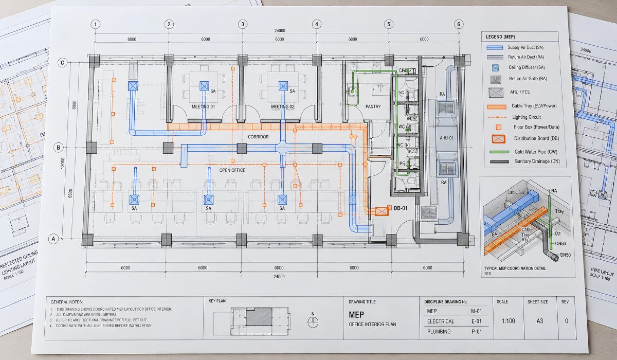
MEP drawings show how building services are arranged in an office and how they relate to the interior design. Understanding the drawing set helps businesses define the scope of work. It also provides a basis for discussing requirements with the responsible parties and checking information before construction.
1. What Are MEP Drawings?
MEP drawings show the mechanical, electrical, and plumbing systems, including equipment locations and service routes. In an office interior design package, the scope depends on the existing conditions and project requirements. The building’s shared systems and any proposed modifications must be clearly distinguished. Low-voltage systems, data networks, and fire protection may be documented in separate drawing packages.
2. The Role of MEP Drawings in Office Design
MEP drawings help businesses, design teams, and contractors agree on how building services will be arranged in the office. The drawing set supports the following tasks:
- Comparing operational needs with the existing building infrastructure and proposed interior layout.
- Identifying intersections between service routes so they can be reviewed and clarified before installation.
- Providing information for quantity takeoffs and defining the scope of a quotation.
- Checking completed work alongside inspection and acceptance documents for the office interior.
- Recording technical information for reference during maintenance or future office modifications.
When approving a design, businesses need to define the full scope of the MEP drawings so related work can proceed. The team preparing the drawings should clarify missing information, unresolved details, or discrepancies with existing conditions before starting.
3. Systems Shown in Office MEP Drawings
The MEP drawing list is determined by the existing systems and project scope. A drawing package may include mechanical, electrical, plumbing, and fire protection drawings. Low-voltage and data systems may be shown separately, depending on the project requirements and the parties responsible for them.
3.1. Mechanical drawings
Mechanical drawings show systems such as air conditioning and ventilation, including equipment, ductwork, and related technical requirements. In an office, the design may involve adjusting air distribution to suit the layout, occupancy, and ceiling design.
The drawings should clarify equipment locations, service routes, and the technical information needed for coordination. The design team should also identify which systems are retained and which require adjustment.
3.2. Electrical drawings
Electrical drawings show the power supply, lighting, equipment, and related routes. In an office, the design may include power outlets, lighting fixtures, distribution boards, and connections for equipment.
The drawings should identify equipment locations, circuit routes, and relevant technical specifications. The design team should coordinate these details with workstations, built-in furniture, partitions, and the ceiling layout.
3.3. Low-voltage and data drawings
Low-voltage and data drawings show systems such as data networks, telephone, access control, and other technology infrastructure. The scope depends on the office’s operational needs and the systems provided by the building.
The drawings should indicate equipment locations, connection points, and cable routes. Different parties may be responsible for coordinating the systems and defining operational requirements.
3.4. Plumbing drawings
Plumbing drawings show water-use points, fixtures, and related pipe routes. In an office, the design scope may focus on the pantry, a private restroom, or areas with water-using equipment.
The drawings should clearly show connection points, routes, and elevations or slopes where required. Hot and cold domestic water supply and condensate drainage are shown according to the design. The relevant disciplines should agree on who documents each system in the drawing package.
3.5. Fire protection drawings
Fire protection drawings show the systems and equipment included in the design scope. Modifications may involve fire alarms, firefighting systems, or other safety requirements when an office is changed.
The drawing list and applicable references should be checked against the building’s fire protection documentation. The applicable fire safety standards and procedures depend on the building, the extent of the changes, and the regulations in force at the time.
4. Types of MEP Drawings by Purpose
MEP drawings can also be classified by their purpose, in addition to being grouped by system. A drawing may serve more than one purpose. For example, an installation drawing may also show coordination information between systems.
4.1. MEP design drawings
MEP design drawings show the system design and technical requirements at each design stage. The package may include layout plans, schematic diagrams, equipment schedules, and necessary technical details.
Construction drawings form part of the construction design documentation. Installation drawings typically clarify how the work should be installed under actual site conditions. When assigning the work, the parties should agree on the drawing package name, level of detail, and handover requirements.
4.2. System coordination drawings
Coordination drawings bring together information from different disciplines to compare the locations and elevations of various systems. They may show how ductwork, pipes, cable trays, and ceiling-mounted equipment relate to the structure and interior design.
A combined plan shows horizontal locations. Areas with limited installation space or multiple intersecting routes may require further review using sections or a model. The responsible team should update the relevant drawings with the coordination results.
4.3. Detailed installation drawings
Detailed installation drawings, or shop drawings, specify how work will be fabricated or installed based on the design documentation and actual site conditions. They may include dimensions, elevations, connection details, and the selected equipment configuration.
The team preparing the drawings should check them against existing conditions and coordinate with the relevant disciplines before submitting them for review. Responsibility for preparing, checking, and approving the drawings should be defined in the contract and project requirements.
4.4. Drawings for openings and wall or floor penetrations
These drawings identify where pipes, cables, or ducts pass through walls and floors. The information should clarify the location, opening dimensions, elevation, and any sleeves required.
Before work begins at a wall or floor penetration, the parties should confirm:
- Structural conditions and the permitted scope of work on the wall or floor.
- Firestopping and waterproofing requirements at the penetration.
- Building management approval and installation conditions, where required.
4.5. Pipe spool drawings
Pipe spool drawings show pipe sections or assemblies for fabrication and installation. They may include dimensions, item codes, and joint information. These drawings are used when the project includes pipe spool fabrication under an agreed construction method.
4.6. As-built MEP drawings
As-built drawings record the actual locations and specifications of systems after construction, including changes from the design documentation. They should accurately represent the installed systems for reference after handover.
During maintenance or renovations, technical teams can use as-built drawings to locate pipe routes and equipment. Changes made during occupancy should also be recorded so the drawings remain consistent with actual conditions.
5. How to Read MEP Drawings in an Office Design Package
Businesses should identify the correct drawing package before reviewing technical details. Starting with the drawing index and then reviewing individual sheets helps place information in context and avoids drawing conclusions from a single sheet.
5.1. Check the drawing index, title block, and revision
Before reviewing the technical content, businesses should check:
- Drawing index: The sheets included in the package and the system covered by each sheet.
- Title block: The project, area, drawing title, sheet number, and responsible company or person.
- Revision: The issue date, revision code, and purpose, such as for discussion, approval, or construction.
Drawings for different purposes may not be identical. Businesses should check whether the relevant sheets reflect the agreed changes. For example, electrical drawings based on an earlier layout should be reviewed again if the office floor plan has changed.
5.2. Check symbols, specifications, and equipment schedules
Symbols and specifications should be read using the drawing package legend. For equipment codes, businesses should refer to the corresponding equipment schedule or technical documentation to confirm the specifications and location shown on the drawing.
| Information to review | Details to clarify |
|---|---|
| Symbols and line types | The equipment or service route shown, and how existing, removed, and new items are distinguished |
| Equipment code | The corresponding item in the equipment schedule, its specifications, and its location on the drawing |
| Dimensions and units | The dimension value, unit used, and the equipment or service route being measured |
| Elevation | The reference datum and whether the elevation is given at the bottom, centerline, or top of the equipment or service route |
| Technical specifications | The capacity, flow rate, or other specified characteristics of the relevant equipment or service route |
5.3. Compare plans, schematic diagrams, sections, and details
The same equipment or service route may appear in several types of drawings. Businesses should review them together to determine locations, connections, elevations, and installation details.
| Drawing type | Information to compare |
|---|---|
| Plan drawing | Horizontal location and route |
| Schematic diagram | Connections or relationships between equipment and system components |
| Section drawing | Elevation relationships in the area under review |
| Detail drawing | Configuration or installation method referenced by the drawing symbol |
When a drawing includes a reference symbol, businesses should check the specific detail sheet it points to. If information about the same location or equipment differs between sheets, the location and discrepancy should be clearly noted for the responsible drawing team to review.
6. Coordinating MEP Drawings with Office Interior Design
MEP and interior drawings should be based on an approved layout and surveyed existing conditions. Reviewing them together helps identify where the interior layout and building services need to be coordinated.
6.1. Ceilings, lighting, and building services
The reflected ceiling plan should be checked against the locations of lights, air outlets, smoke detectors, and fire sprinklers. The design team should clarify service elevations, structural conditions, and ceiling construction to determine the available space.
The drawings should also show how equipment can be accessed for inspection and maintenance. Access panels, removable components, and access routes should be arranged to suit the ceiling or enclosing interior elements.
6.2. Workstations, power, and data infrastructure
Workstation layouts should be checked against the power and data infrastructure and the lighting plan, including:
- Power outlets and data points: Check their locations in relation to desks, cabinets, and equipment.
- Power and data cable routes: Compare them with partitions, floors, and furniture to determine how services will reach each area.
- Lighting controls: Divide controls by room function and usage.
- Lighting requirements: Compare office lighting standards with equipment specifications and the proposed layout.
- Potential for additional workstations: Check available power capacity, connection points, and spare capacity.
6.3. Air conditioning zones, ventilation, and noise sources
When rooms are divided or occupancy levels change, the design team should review the air conditioning and ventilation zones. Supply and return air outlets should be checked against partitions, doors, and occupied areas.
Noise and vibration from mechanical and electrical equipment should be reviewed at the installation location and along the transmission path to work areas. Any mitigation measures should be coordinated with the ceiling, partitions, and related components, taking the design conditions into account.
6.4. Water-use areas and connection points
The layout of pantry areas or water-using equipment should be checked against the existing water supply and drainage points. Pipe elevations, routes, and access to connection points may affect the interior design.
The drawings should clarify the boundary between the building’s systems and the work carried out by the business. For wall or floor penetrations, the parties should confirm structural requirements and the treatment method before work begins.
6.5. Floor layout and fire safety requirements
Changes to partitions, enclosed rooms, or ceilings may affect equipment locations and fire safety measures. The design team should coordinate smoke detector and sprinkler locations, escape routes, and related safety requirements with the proposed interior layout.
The parties should determine the building’s construction approval requirements and the fire safety design appraisal requirements that apply to the project scope and relevant authority. Documentation requirements and responsibilities should be clarified under current regulations before modifications begin.
7. Checklist for Reviewing MEP Drawings Before Construction and Handover
When agreeing on the scope of office design and construction, businesses should specify the drawing package to be provided and the review milestones. At each milestone, drawings should be checked against existing conditions, project requirements, and the relevant confirmation documents.
| Timing | Items to compare | Related documents or confirmations |
|---|---|---|
| Before design starts | Existing conditions, connection points, and systems permitted for use | Building documentation, survey results, and confirmed technical information |
| When confirming the scope of work | Systems to be retained, removed, or newly installed, and each party’s responsibilities | Contract scope, drawing index, and responsibility allocation |
| Before issuing drawings for use | Sheet numbers, revisions, issue status, and superseded sheets | Issue register, revision details, and confirmation under the project process |
| Before construction of relevant work | Technical references, building conditions, and applicable legal requirements | Approved documentation, construction requirements, and procedures for the work |
| Before installation | Locations, dimensions, elevations, equipment information, and unresolved items | Design documentation, installation drawings, and coordination clarifications |
| Before closing up work | Inspection results and actual information to be recorded | Inspection records, measurements, photographs, and relevant updated drawings |
| When changes occur | Effects on systems and drawings requiring revision | Reviewed change details, revised sheets, and approval records |
| At handover | As-built drawings and technical documents corresponding to the completed work | Handover index, acceptance records, equipment documentation, and operating information as agreed |
The contract and project requirements should clearly identify who prepares, checks, and approves the documentation. During acceptance, the parties should verify that the drawing package is complete and compare the completed work with the drawings and relevant inspection and testing records.
8. BIM and Automation in MEP Drawing Management
Building Information Modeling (BIM) is a method of creating and managing building information using a digital model. In MEP design, BIM supports data organization and coordination between disciplines. Its scope should match the documentation requirements and available resources.
8.1. Model coordination and document updates
A coordinated model helps teams review the relationships between building services and the structure. Clash detection tools can identify, display, and report intersections that the responsible engineers need to review.
Drawings and schedules linked to the model may update when the model changes. Before issuing the documentation, the team preparing it still needs to check the display settings, content, and consistency between the drawings, schedules, and model.
8.2. Data requirements and limits of automation
Review results depend on the completeness of the model, the input data, and the checking configuration. Automated clash detection does not mean artificial intelligence (AI) can independently select an appropriate solution. Engineers need to assess the technical requirements before revising the design.
When MEP data is used in a building management system (BMS), the parties should separately agree on connection requirements and equipment information. As-built drawings should be organized with operational data to support the agreed integration scope.
Businesses should coordinate the MEP drawing scope with the interior design and building conditions. Before construction, the parties should clarify existing conditions, responsibilities, and the drawing revision to be used. As-built drawings should accurately reflect the installed systems to support office management, maintenance, and renovation.
9. Frequently Asked Questions (FAQ)
9.1. Does a small office need MEP drawings?
The need for drawings depends on the technical work involved and the building’s requirements. Even a small office may need relevant documentation when electrical, air conditioning, data, or fire protection systems are changed. If a system is retained, the parties should identify the existing conditions and any modifications that need to be documented.
9.2. Which party is responsible for preparing office MEP drawings?
An MEP consultant or technical team prepares the design within the scope of its contract. A contractor may prepare installation drawings when assigned to do so. Businesses should confirm who is responsible for each system and who reviews the documentation, especially for work handled by the building or a technology provider.
9.3. How is the cost of preparing MEP drawings determined?
The cost depends on the floor area, the number of systems to be designed, existing conditions, and the level of detail required. When requesting a quotation, businesses should clarify whether it includes surveys, calculations, coordination, revisions, and the handover format. The scope of documentation should be comparable across proposals.
9.4. Can old as-built MEP drawings be used for an office renovation?
They can be used as a starting point after being checked against existing conditions. Older documentation may not include changes made during occupancy. Before developing a renovation design, the responsible team should verify which systems will be retained, connection points, and any information that remains unconfirmed.
9.5. Should businesses receive PDF files, DWG files, or a BIM model?
The handover format should be agreed based on its intended use and the contract. PDF files are convenient for viewing, while DWG files or BIM models support use and editing in the corresponding software. The parties should confirm the software version, accompanying data, and rights to use the documentation.